1. Vor-CNC-Bearbeitung: Design Preparation for Electric Razor Hand Plates
Before initiating CNC-Bearbeitung for the electric razor hand plate prototype, Eine umfassende Entwurfsphase ist von entscheidender Bedeutung, um sie an die Funktions- und Benutzeranforderungen anzupassen. Diese Phase folgt einem linearen Prozess mit klaren Schwerpunktbereichen, wie unten beschrieben.
| Design Step | Hauptanforderungen | Recommended Materials |
| Product Demand Analysis | Support high-speed tool head rotation (thousands of RPM); reserve space for motor, knife mesh, blade, battery compartment, and Type-C charging interface; ensure ergonomic non-slip grip and lightweight design. | – |
| Structural Design | Hand plate integration with razor body: design detachable/integrated tool head; control knife mesh-blade gap (0.1-0.2mm); reserve holes for switch, indicator lights, and charging port; add internal supports for motor/circuit board stability under vibration. | – |
| Materialauswahl | Match mass production standards; prioritize durability, Bearbeitbarkeit, and user comfort. | Hand plate housing: ABS plastic (leicht, dyeable), PC (clear/matte), Aluminiumlegierung (High-End); Tool head parts: Stainless steel/nickel alloy (knife mesh), ceramic/metal (blade); Internal supports: Acrylic/ABS. |
| 3D-Modellierung & Zeichnung | Use SolidWorks/UG to create 3D models with key dimensions (z.B., hand plate thickness, tool head diameter, battery compartment size); export STL (3D-Druck) or DXF (CNC-Bearbeitung) Dateien. | – |
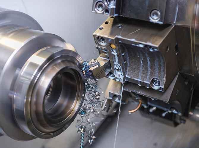
2. Core CNC Machining Process for Electric Razor Hand Plates
Der CNC machining process transforms design blueprints into physical hand plate components. It requires strict material preparation, step-by-step execution, and precision control to meet razor performance standards.
2.1 Materialvorbereitung: Selecting Base Materials
Material choice directly impacts hand plate durability, Gewicht, and machining efficiency. Nachfolgend finden Sie einen Vergleich gängiger Materialien:
| Materialtyp | Optionen | Dickenbereich | Application Scenarios |
| Plastic Parts | ABS sheet/rod | 2-3mm | Hand plate housing (kostengünstig, leicht zu bearbeiten) |
| Metal Parts | Aluminum alloy sheet, stainless steel sheet | 1-2mm (stainless steel for knife mesh; aluminum for high-end housings) | Tool head components (knife mesh, blade holders), high-end hand plate housings. |
2.2 Step-by-Step CNC Machining Execution
Follow this linear workflow to ensure consistent precision:
- Programmierung & Path Planning: Use Mastercam/PowerMill to generate tool paths. For hand plate housing: Use large-diameter tools (z.B., φ8mm flat cutters) for roughing; small-diameter tools (z.B., φ0.3mm ball cutters) zum Abschluss (z.B., switch holes, charging port edges). For tool head parts: Set high precision (Toleranz ±0,05 mm) to ensure uniform knife mesh-blade gap.
- Clamping & Positionierung: Secure materials with a vise/vacuum cup. For curved hand plate edges, use 4-axis/5-axis linkage machining; calibrate center position for symmetrical parts (z.B., dual-tool head hand plates).
- Bearbeitungsausführung:
- Housing: Mill outer shape, reserve switch/indicator/charging holes; add non-slip texture grooves on grip areas.
- Internal Structure: Mill motor mounting slots, battery compartment (with size matching Type-C interface), circuit board card slots.
- Tool Head Interface: Machine knife mesh mounting grooves (ensure flatness/verticality) and blade holder holes (z.B., M2 threaded holes for fixing).
- Preliminary Surface Check: Remove burrs; verify hole positions and groove depths before post-processing.
2.3 Critical Process Control
To avoid functional defects, focus on these two key controls:
- Toleranzkontrolle: Tool head gap tolerance ±0.02mm (prevents blade-knife mesh friction); hand plate housing size tolerance ±0.1mm (ensures component fit).
- Oberflächenglätte: For grip areas, achieve Ra 1.6μm surface roughness via finishing; avoid sharp edges (chamfer 0.5mm) to enhance comfort.
3. Nachbearbeitung: Oberflächenbehandlung & Montage
Nach der CNC-Bearbeitung, post-processing enhances aesthetics and functionality, while assembly turns parts into a usable prototype.
3.1 Oberflächenbehandlung: Material-Specific Processes
Different materials require tailored treatments to meet user and performance needs:
| Part Type | Treatment Method | Zweck & Effect |
| Plastic Hand Plate Housing | Sprühen | Apply matte paint (non-slip grip) or piano paint (high-gloss texture); common colors: Schwarz, Silber, or custom shades. |
| Silk Screen | Print brand logos, switch symbols (z.B., power icon), and charging indicators (z.B., battery level marks) on visible areas. | |
| Metal Tool Head Components | Polieren (Edelstahl) | Smooth knife mesh surface (prevents skin irritation); remove machining scratches. |
| Abschrecken & Härten (Blade) | Increase blade hardness (HRC 55-60) for long-lasting sharpness. | |
| Aluminum Alloy Housing | Anodization/Sandblasting | Anodization (anti-corrosion); Sandstrahlen (sanfte Berührung, fingerprint-resistant). |
3.2 Component Testing & Assembly Checklist
Ensure prototype functionality with this step-by-step verification and assembly process:
- Functional Verification:
- Install DC brushed/brushless motor; test tool head rotation speed (z.B., 3000-5000 U/min) and stability (no abnormal vibration).
- Connect Type-C charging interface; verify LED indicator accuracy (z.B., red = charging, green = full).
- Test switch feel (stroke 1-1.5mm) and responsiveness (no stuck issues).
- Assembly Process:
- Fix motor, circuit board, and battery on internal acrylic/ABS supports; secure wires with cable ties (prevent vibration damage).
- Attach knife mesh to tool head interface (ensure 0.1-0.2mm gap with blade); fix blade holder with M2 screws.
- Assemble hand plate housing and bottom cover: Use snaps (for easy disassembly) or ultrasonic welding (für Wasserbeständigkeit); seal gaps with silicone gaskets (optional, for washable designs).
4. Prototype Optimization & Iteration
Based on user testing and functional feedback, optimize the hand plate prototype to resolve issues and improve usability.
| Problem Feedback | Improvement Direction |
| Tool head vibration during use (causes discomfort). | Add silicone shock-absorbing pads under the motor; reinforce internal support rigidity (z.B., add rib structures). |
| Knife mesh-blade misalignment (causes uneven shaving). | Adjust CNC machining parameters for tool head grooves; use laser measurement to calibrate gap before assembly. |
| Hand plate grip discomfort (slippery/heavy). | Add rubber non-slip strips on grip areas; switch to lightweight PC material (reduces weight by 10-15%). |
| Charging interface damage (frequent plugging). | Design a recessed Type-C port (1-2mm Tiefe) or add a rubber protective cover. |
5. Common Technical Difficulties & Lösungen
During CNC machining and prototype production, these issues often arise—here are practical fixes:
| Technical Difficulty | Lösung |
| Uneven knife mesh-blade gap. | Use 4-axis CNC machining for tool head grooves; Nachbearbeitung, use a feeler gauge to adjust gap (add shims if needed). |
| Motor vibration causes noise. | Optimize internal support design (z.B., use metal brackets instead of plastic); add foam damping pads around the motor. |
| Plastic hand plate housing deformation (after machining). | Choose fiber-reinforced ABS (increases strength by 20%); add stiffeners at edge/corner areas. |
| Charging port hole misalignment (affects plug fit). | Use CNC machining with positional accuracy ±0.03mm; pre-mark hole positions on 3D models for verification. |
6. Lieferung & Subsequent Applications
A well-executed hand plate prototype serves multiple purposes to support product development:
- Anzeige & Testen: Use for marketing demos (z.B., trade shows), customer feedback collection (z.B., grip comfort surveys), and appearance validation (ensure design matches brand image).
- Data Inheritance: Share CNC machining parameters (z.B., Werkzeugwege, tolerance settings) and problem records (z.B., vibration solutions) with the mass production team. This optimizes injection mold design (for plastic hand plates) or metal die-casting processes (for aluminum parts), reducing mass production risks.
Yigu Technology’s Viewpoint
Bei Yigu Technology, we recognize CNC machining is the core of creating high-performance electric razor hand plate prototypes. It ensures the hand plate’s ergonomics, Präzision, and durability—all critical for user satisfaction. When manufacturing such prototypes, we prioritize two aspects: material-machinability matching (z.B., using ABS for cost-effective housings, stainless steel for corrosion-resistant knife meshes) and functional validation (z.B., rigorous vibration and gap testing). By combining precise CNC processes with iterative optimization, we help clients shorten development cycles and avoid mass production pitfalls. Moving forward, we will integrate AI-driven tool path optimization to further 提升 machining efficiency while maintaining ±0.02mm tolerance levels, supporting faster prototype iterations for electric razor brands.
FAQ
- What is the ideal gap between the knife mesh and blade in a CNC machined electric razor hand plate prototype, and how is this achieved via CNC machining?
The ideal gap is 0.1-0.2mm (prevents skin irritation while ensuring effective shaving). This is achieved by setting CNC machining tolerance of ±0.05mm for tool head grooves, using 4-axis machining for groove flatness, and post-machining gap verification with a feeler gauge.
- Can CNC machined electric razor hand plate prototypes be used directly for small-batch production?
NEIN. CNC prototypes are for design testing and feedback collection. Für die Produktion von Kleinserien, switch to injection molding (for plastic hand plates) or die-casting (für Metallteile)—these processes are more cost-effective and efficient for high-volume manufacturing, using data from CNC prototypes to optimize tooling.
- How long does it take to produce a CNC machined electric razor hand plate prototype?
It depends on design complexity. For a standard hand plate (plastic housing + metal tool head interface), the process takes 5-8 Tage (including design finalization, CNC-Bearbeitung, Nachbearbeitung, und Montage). Für komplexe Designs (z.B., 4-axis machined curved housings, waterproof structures), it may take 10-12 Tage.