1. Vor-CNC-Bearbeitung: Design Foundation for Prototypes
Bevor es losgeht CNC-Bearbeitung, Eine solide Designphase ist unerlässlich, um sicherzustellen, dass der Prototyp die funktionalen und strukturellen Anforderungen erfüllt. Diese Phase umfasst vier Kernschritte, jeweils mit klaren Zielen und Materialien.
| Design Step | Hauptanforderungen | Recommended Materials |
| Product Demand Analysis | Achieve constant temperature (40-50°C), einstellbare Temperatur, Timing-Funktion; reserve space for heating elements, Sensoren, Leiterplatten, and battery compartments. | – |
| Structural Design | Create an ergonomic curved shell to fit eye contours; design detachable enclosures (snaps/screws) for easy internal component assembly. | – |
| Materialauswahl | Prototype materials should align with mass production standards. | Housing: ABS plastic (easy to process/dye), PC (clear/matte), Aluminiumlegierung (High-End); Heating element: Thin metal sheet, electric heating film; Internal support: ABS, Acryl. |
| 3D-Modellierung & Zeichnung | Generate 3D models with dimensional tolerances (z.B., shell thickness 1.5-2mm, gap 0.5mm); export STL (for 3D printing) or 2D files (DXF/DWG for CNC machining). | – |
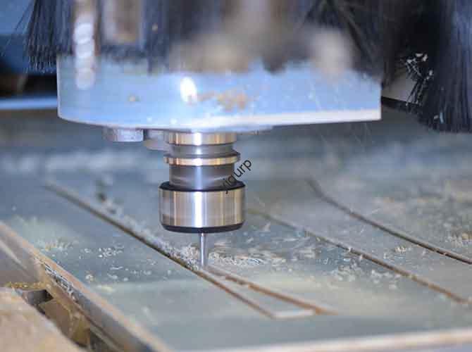
2. Core CNC Machining Process for Eye Instrument Prototypes
Der CNC machining process transforms design drawings into physical parts. It requires precise material preparation, step-by-step execution, and strict process control to ensure accuracy and functionality.
2.1 Materialvorbereitung: Choose the Right Base
The choice of material directly affects the prototype’s performance and appearance. Below is a comparison of common materials for plastic and metal parts:
| Materialtyp | Optionen | Dickenbereich | Application Scenarios |
| Plastic Parts | ABS plate/rod | 1.5-3mm | Main housing (kostengünstig, leicht zu bearbeiten) |
| Metal Parts | Aluminum alloy plate, stainless steel plate | Depends on design | Heat dissipation structures, dekorative Teile (hohe Haltbarkeit) |
2.2 Step-by-Step CNC Machining Execution
Follow this linear process to ensure consistent and high-quality machining:
- Programmierung & Path Planning: Use CAM software (Mastercam, PowerMill) to generate tool paths. Set parameters like safety height, feed speed, und Schnitttiefe. Use large-diameter tools (z.B., φ6mm flat cutters) for roughing (schneller Materialabtrag) and small-diameter tools (z.B., φ0.5mm ball cutters) zum Abschluss (detail preservation).
- Clamping & Positionierung: Secure materials with a vise or vacuum cup to prevent displacement. For symmetrical structures, calibrate the center position to ensure left-right consistency.
- Bearbeitungsausführung:
- Housing: Mill the shape layer by layer, retaining buttons, display openings, and heat dissipation holes.
- Internal Structure: Mill battery compartments, circuit board slots, and heating element fixing positions.
- Oberflächenbehandlung: Achieve matte or glossy finishes via high-speed finishing (avoids secondary polishing).
2.3 Critical Process Control
To meet prototype standards, focus on two key controls:
- Toleranzkontrolle: Enclosure size tolerance is strictly controlled at ±0.1mm to ensure proper assembly with internal components.
- Temperature Simulation: For heating functions, machine grooves or thermal columns inside the enclosure to optimize heat conduction paths.
3. Nachbearbeitung: Oberflächenbehandlung & Montage
Nach der CNC-Bearbeitung, post-processing and assembly turn individual parts into a functional prototype.
3.1 Oberflächenbehandlung: Enhance Aesthetics & Funktionalität
Different part materials require specific surface treatments to improve usability and appearance:
| Part Type | Treatment Method | Zweck & Effect |
| Plastic Parts | Sprühen | Apply matte paint (non-slip) or piano paint (hochglänzend); use soothing colors (light blue, off-white). |
| Silk Screen | Print brand logos and operation icons (z.B., “+” “-” for temperature control) on the shell surface. | |
| Metal Parts | Anodization | Improve corrosion resistance. |
| Sandstrahlen | Enhance tactile feel. |
3.2 Component Testing & Montage
Follow this checklist to ensure the prototype works properly:
- Functional Verification:
- Install analog heating plates (z.B., electric heating films) to test temperature control circuit response speed and temperature uniformity.
- Debug timing functions (z.B., 5-minute automatic shutdown); check button feel and LED indicator light transmission.
- Assembly Process:
- Attach the circuit board, Batterie, and heating element to the internal bracket; connect wires.
- Assemble the housing and cover with screws or snaps to ensure a tight seal (prevents dust entry).
4. Prototype Optimization & Iteration
No prototype is perfect on the first try. Gather feedback and make targeted improvements to enhance performance and user experience.
| Problem Feedback | Improvement Direction |
| Housing edge chamfers are not smooth (affects touch comfort). | Optimize housing curvature to reduce eye area oppression. |
| Local overheating (poor heating efficiency). | Adjust internal air duct design to improve heat dissipation. |
| Inconvenient charging. | Add magnetic charging ports (z.B., Type-C) to enhance user experience. |
5. Lieferung & Subsequent Applications
A well-made prototype serves multiple purposes and provides valuable data for mass production.
- Display Purposes: Use the prototype for marketing promotions, customer presentations, and appearance verification (ensures the design meets market expectations).
- Data Inheritance: Share CNC machining parameters and problem records with the mass production team to optimize injection mold design or metal die-casting processes (reduces mass production risks).
6. Common Technical Difficulties & Lösungen
During CNC machining and prototype production, you may encounter technical issues. Here are practical solutions:
| Technical Difficulty | Lösung |
| Low accuracy when machining complex surfaces. | Use 4-axis/5-axis CNC machines with high-precision tools (z.B., Diamantbeschichtete Werkzeuge). |
| Uneven temperature control in the prototype. | Machine heat transfer grooves inside the enclosure or use thin heating plates with aluminum heat sinks. |
| Plastic housing is prone to deformation. | Choose high-strength ABS or PC materials; optimize heat treatment (z.B., Glühen). |
| Poor button feel. | Design silicone button pads or raised buttons; increase button travel space during CNC machining. |
Yigu Technology’s Viewpoint
Bei Yigu Technology, we believe CNC machining is the cornerstone of high-quality electric heating compress eye instrument prototypes. It bridges design concepts and physical products, Gewährleistung jedes Detail (from tolerance control to surface finish) aligns with user needs. When creating such prototypes, we prioritize material compatibility (matching mass production standards) and functional verification (especially temperature stability, a core feature of eye instruments). By combining precise CNC machining with iterative optimization, we help clients reduce development cycles and improve product market adaptability. Moving forward, we will integrate more intelligent technologies (z.B., AI-driven machining path optimization) to further enhance prototype accuracy and production efficiency.
FAQ
- What is the ideal temperature range for the electric heating compress eye instrument prototype, and how does CNC machining support this?
The ideal temperature range is 40-50°C. CNC machining supports this by creating precise internal grooves/thermal columns (optimizing heat conduction) and ensuring tight assembly (preventing heat loss), which helps maintain temperature uniformity.
- Can CNC machined prototypes for electric heating eye instruments be directly used for small-batch production?
In den meisten Fällen, NEIN. CNC machined prototypes are mainly for design verification and functional testing. Für die Produktion von Kleinserien, you need to switch to more cost-effective processes (z.B., injection molding for plastic parts) based on prototype data.
- How long does it take to produce a CNC machined electric heating compress eye instrument prototype?
It depends on design complexity and material type. Typischerweise, the process (from design finalization to prototype assembly) takes 7-14 Tage. Simple designs with plastic parts may take 5-7 Tage, while complex designs with metal parts (and multiple iterations) may take 2-3 Wochen.