FDM-Grundlagen
Fused Deposition Modeling ist ein wichtiger Bestandteil der modernen additiven Fertigung. Dabei wird geschmolzenes Material auf einem geplanten Weg platziert, Schicht für Schicht, ein reales Objekt aus einer Computerdatei erstellen. Diese Technologie ist nicht nur etwas für Bastler; Es verändert die Technik, Produktdesign, und Fertigung, indem wir die Dinge schneller und flexibler als je zuvor machen.
Wichtige Begriffe
Um die Fused Deposition Modeling zu verstehen, Es ist wichtig zu wissen, wo es in die Branche passt. Stellen Sie sich diese Begriffe so vor: “Fahrzeug” ist die große Kategorie, “Auto” ist ein bestimmter Typ, Und “Limousine” ist ein besonderes Modell.
- Additive Fertigung (BIN): Dies ist der Branchenbegriff für den Gesamtprozess des schichtweisen Aufbaus von Objekten aus Computerdaten. Es ist das “Fahrzeug.”
- 3D Drucken: Dies ist der gebräuchlichere Begriff, den die meisten Menschen für die additive Fertigung kennen, Wird häufig von Verbrauchern und kleinen Unternehmen verwendet. Es ist das “Auto.”
- Modellierung der Schmelzablagerung (FDM): Das ist ein Spezifisches, markenrechtlich geschützter Typ des additiven Herstellungsverfahrens, bei dem Kunststofffilamente verwendet werden. Es ist das “Limousine.” Der allgemeine Begriff ist Fused Filament Fabrication (FFF).
Wie es funktioniert
Der Prozess ist von der Idee her einfach. Ein langer Strang aus festem Kunststoffmaterial, Filament genannt, wird von einer Spule in einen beheizten Teil des Druckers, den sogenannten Extruder, eingespeist. Der Extruder schmilzt das Filament und drückt es durch eine kleine Öffnung, die Düse genannt wird. Das Bewegungssystem des Druckers, Normalerweise arbeite ich an X, Y, und Z-Richtung, bewegt den Extruderkopf, um einen Querschnitt des Objekts zu zeichnen, Platzieren Sie eine dünne Linie aus geschmolzenem Kunststoff. Diese Schicht kühlt fast sofort ab und härtet aus, an der darunter liegenden Schicht kleben. Dieser Vorgang wiederholt sich, Schicht für Schicht, bis das ganze Objekt fertig ist.
Auswirkungen auf die Fertigung
Die Bedeutung des Fused Deposition Modeling liegt in seiner Vielseitigkeit und Benutzerfreundlichkeit. Es hat die Arbeitsweise vieler Branchen durch die Bereitstellung leistungsstarker Fähigkeiten völlig verändert:
- Schnelles Prototyping: Reduziert die Zeit zwischen dem ersten Entwurf und einem physischen Modell erheblich, Lassen Sie Ingenieure und Designer die Form testen, fit, und funktionieren in Stunden statt in Wochen.
- Kundenspezifische Werkzeuge und Vorrichtungen: Ermöglicht die bedarfsgesteuerte Erstellung von Fertigungshilfen, die die Effizienz und Genauigkeit traditioneller Prozesse wie Montage und Bearbeitung verbessern.
- Kleinserienfertigung: Ermöglicht die kostengünstige Herstellung von Endverbrauchsteilen ohne die enormen Vorlaufkosten und Wartezeiten, die mit Spritzguss oder anderen Massenproduktionsmethoden verbunden sind.
- Herstellung für jedermann zugänglich machen: Seine niedrigen Kosten haben kleinen Unternehmen leistungsstarke Fertigungsmöglichkeiten eröffnet, Forschungslabore, Schulen, und sogar Einzelpersonen.
Gemessen an den verkauften Einheiten macht die FDM-Technologie durchweg den größten Anteil am Markt für additive Fertigung aus. Laut Marktstudien, wie die von Grand View Research, Es wird erwartet, dass der FDM-Sektor weiterhin stark wachsen wird, angetrieben durch Verbesserungen bei Materialien und Hardware, die den Einsatzbereich vom Prototyping auf die Herstellung funktionsfähiger Teile erweitern.
Der FDM-Prozess
Für jeden, der diese Technologie nutzen möchte, ist es wichtig, den Arbeitsablauf von einer digitalen Idee bis zu einem realen Objekt zu verstehen. Der Prozess lässt sich in fünf klare Schritte unterteilen.
Schritt 1: Digitale Blaupause
Alles beginnt mit einem digitalen Modell. Dies wird normalerweise mithilfe von Computer-Aided Design erstellt (CAD) Software. Sobald das 3D-Modell fertig ist, es ist gespeichert, normalerweise als STL- oder OBJ-Datei. Dieses Dateiformat beschreibt die Oberflächenform des Objekts als Netz aus Dreiecken.
Diese Mesh-Datei wird dann in ein spezielles Programm namens a importiert “Allesschneider.” Slicer-Software, wie Cura oder PrusaSlicer, ist die entscheidende Verbindung zwischen dem 3D-Modell und dem Drucker. Es “Scheiben” Das Modell wird in Hunderte oder Tausende von horizontalen Schichten unterteilt und die spezifischen Maschinenanweisungen erstellt, bekannt als G-Code, Das wird jede Bewegung des Druckers leiten. Im Slicer, Der Bediener legt alle wichtigen Druckeinstellungen fest: Schichthöhe, Füllungsdichte und -muster, Druckgeschwindigkeit, und Temperaturen für die Düse und die Bauplatte.
Schritt 2: Maschinenvorbereitung
Bevor der Druck beginnen kann, Die Maschine muss vorbereitet werden. Dabei muss sichergestellt werden, dass die Bauplatte – die Oberfläche, auf der das Teil gedruckt wird – sauber und eben ist. Für Materialien, die zum Verziehen neigen, Um die Haftung der ersten Schicht zu unterstützen, kann ein Klebstoff wie ein Klebestift oder eine spezielle Beschichtung aufgetragen werden. Auf dem Drucker wird eine Spule des gewählten Filamentmaterials montiert, und das Ende des Filaments wird in den Extrudermechanismus eingeführt, bis es die beheizte Düse erreicht.
Schritt 3: Erhitzen und Platzieren von Material
Mit geladenem G-Code und vorbereiteter Maschine, Der Druckvorgang beginnt. Der “heißes Ende,” Das ist der Heizblock und die Düsenbaugruppe, erhitzt das Filament auf seinen spezifischen Schmelzpunkt, Die Temperatur kann zwischen etwa 200 °C für PLA und über 400 °C für Hochleistungskunststoffe liegen.
Das Bewegungssystem, bestehend aus Motoren, Gürtel, und Leitspindeln, Steuert präzise die Bewegung des Extruders in X- und Y-Richtung, um die erste Schicht nachzuzeichnen. Sobald es fertig ist, Die Bauplatte oder das Bewegungssystem bewegt sich geringfügig in Z-Richtung (gleich der Schichthöhe), und der Vorgang wiederholt sich für die nächste Schicht. Der Drucker platziert das Material sorgfältig, Schicht für Schicht, das Objekt von Grund auf aufbauen.
Schritt 4: Kühlen und Härten
Dabei wird der geschmolzene Kunststoff aus der Düse herausgedrückt, es beginnt abzukühlen und auszuhärten, an der darunter liegenden Schicht kleben. Diese Verklebung verleiht dem fertigen Teil seine Festigkeit. Die Abkühlgeschwindigkeit ist eine kritische Prozessvariable. Die meisten FDM-Drucker verfügen über einen speziellen Lüfter, der den Luftstrom auf die neu platzierte Schicht richtet. Dadurch härtet das Material schnell aus, was schärfere Details ermöglicht, bessere Überhänge, und schnellere Druckgeschwindigkeiten. Jedoch, Zu viel Kühlung kann die Verbindung zwischen den Schichten schwächen, Daher ist es wichtig, die richtige Balance zu finden.
Schritt 5: Abschluss
Sobald die letzte Schicht platziert ist, Der Drucker beendet seinen Zyklus, und das Teil lässt man vollständig abkühlen. Anschließend wird das fertige Objekt von der Bauplatte entfernt, Manchmal ist ein Schaber oder Spatel erforderlich.
Wenn das Modell komplexe Überhänge oder Hohlprofile hatte, es wurde wahrscheinlich mit Stützstrukturen gedruckt. Diese temporären Gerüstelemente müssen entfernt werden. Abreißstützen werden von Hand oder mit Werkzeugen abgeknickt. Lösliche Träger, mit einem anderen Material bedruckt, werden in einem bestimmten Lösungsmittel gelöst, Hinterlässt eine saubere Oberfläche. Abhängig von der Anwendung, weitere Veredelungsschritte können durchgeführt werden, wie zum Beispiel Schleifen, um Schichtlinien zu glätten, Dampfglättung (für Materialien wie ABS) um ein glänzendes Finish zu erzielen, oder malen.
Leitfaden zu FDM-Materialien
Das Material ist das “Kraftstoff” des FDM-Prozesses, Und die riesige Auswahl an verfügbaren Kunststoffen ist eine der größten Stärken der Technologie. Die Wahl des richtigen Materials ist entscheidend, da es die Kosten bestimmt, Stärke, Temperaturbeständigkeit, und Gesamtleistung des letzten Teils.
Standardkunststoffe
Das sind die erschwinglichen, benutzerfreundliche Arbeitspferde des FDM, Geeignet für ein breites Anwendungsspektrum vom Prototyping bis hin zu Hobbyprojekten.
- PLA (Polymilchsäure): Das beliebteste FDM-Material. Es ist einfach zu drucken, erfordert kein beheiztes Bett, hat minimale Verformungen, und ist in einer großen Farbvielfalt erhältlich. Es ist auch unter industriellen Kompostierungsbedingungen biologisch abbaubar.
- ABS (Acrylnitril-Butadien-Styrol): Stärker, haltbarer, und temperaturbeständiger als PLA. Es handelt sich um den gleichen Kunststoff, der auch in LEGO-Steinen verwendet wird. Es erfordert ein beheiztes Bett und eine geschlossene Druckkammer, um Verformungen und Risse zu verhindern.
- PETG (Polyethylenterephthalat-Glykol): Bietet eine tolle Ausgewogenheit der Eigenschaften. Es lässt sich fast so einfach drucken wie PLA, bietet aber eine höhere Festigkeit, Haltbarkeit, und Temperaturbeständigkeit, nähert sich der Leistung von ABS. Es ist außerdem für seine hervorragende Chemikalienbeständigkeit und Lebensmittelsicherheit bekannt.
Hochleistungskunststoffe
Diese technischen Materialien werden für anspruchsvolle Anwendungen verwendet, bei denen mechanische Festigkeit erforderlich ist, chemische Beständigkeit, und Hochtemperaturleistung erforderlich sind. Sie benötigen oft Spezialisierung, Hochtemperaturdrucker.
- Nylon (PA): Bekannt für seine außergewöhnliche Zähigkeit, Haltbarkeit, und reibungsarme Eigenschaften. Es ist ideal zum Drucken von Funktionsteilen wie Zahnrädern, lebende Scharniere, und andere Verschleißteile.
- Polycarbonat (PC): Eines der stärksten Materialien, die für Desktop-FDM verfügbar sind. Es verfügt über eine unglaubliche Schlagfestigkeit und Hochtemperaturbeständigkeit, Dadurch eignet es sich für funktionale Prototypen und Endverbrauchsteile, die rauen Umgebungen standhalten müssen.
- SPÄHEN & Schmalz: Teil der PAEK-Familie ultraleistungsfähiger Polymere. Diese Materialien bieten metallähnliche Festigkeit, extreme Temperatur- und Chemikalienbeständigkeit, und sind von Natur aus schwer entflammbar. Sie werden in der anspruchsvollsten Luft- und Raumfahrt eingesetzt, Automobil, und medizinische Anwendungen.
Flexible und zusammengesetzte Filamente
Diese Materialien erweitern die Möglichkeiten von FDM über starre Kunststoffe hinaus, Ermöglicht die Erstellung von Teilen mit einzigartigen Eigenschaften.
- TPU/TPE: Dabei handelt es sich um thermoplastische Elastomere, die sich wie Gummi verhalten. Sie dienen der flexiblen Gestaltung, stoßabsorbierende Teile wie Dichtungen, Dichtungen, Handyhüllen, und tragbare Prototypen.
- Verbundfilamente: Dabei handelt es sich um unedle Kunststoffe (wie PLA, PETG, oder Nylon) die zur Verbesserung ihrer Eigenschaften mit kurzen Strängen anderer Materialien vermischt wurden. Mit Kohlenstofffasern gefüllte Filamente bieten eine deutlich erhöhte Steifigkeit und Festigkeit, während glasgefüllte Filamente die thermische und Dimensionsstabilität verbessern. Andere Verbundwerkstoffe, wie holzgefüllte oder metallgefüllte Filamente, werden hauptsächlich für das Aussehen verwendet.
| Material | Schlüsseleigenschaften | Allgemeine Anwendungen | Druckanforderungen |
| PLA | Einfach zu drucken, starr, gutes Detail, biologisch abbaubar | Visuelle Prototypen, Konzeptmodelle, nicht funktionsfähige Teile | Niedrigtemperaturdüse (190-220°C), kein beheiztes Bett nötig |
| ABS | Stark, dauerhaft, hohe Temperaturbeständigkeit | Funktionsteile, Schutzgehäuse, Automobil-Prototypen | Hochtemperaturdüse (230-260°C), beheiztes Bett (100-110°C), Gehäuse |
| PETG | Stark, dauerhaft, gute chemische Beständigkeit, geringe Schrumpfung | Mechanische Teile, lebensmittelechte Behälter, Schutzkomponenten | Düse für mittlere und hohe Temperaturen (230-250°C), beheiztes Bett (70-80°C) |
| Nylon (PA) | Hart, flexibel, verschleißfest, geringe Reibung | Getriebe, lebende Scharniere, Werkzeuge, langlebige Komponenten | Hochtemperaturdüse (240-270°C), beheiztes Bett, feuchtigkeitsempfindlich |
| PC | Sehr stark, hohe Schlag- und Temperaturbeständigkeit | Funktionsprototypen, Schutzausrüstung, Drohnenteile | Düse für sehr hohe Temperaturen (260-310°C), beheiztes Bett (>110°C), Gehäuse |
| TPU | Sehr flexibel, gummiartig, stoßabsorbierend | Robben, Dichtungen, flexible Prototypen, Handyhüllen | Spezifische Druckgeschwindigkeiten, Direktantriebsextruder empfohlen |
| Kohlefaser | Sehr steif, hohes Festigkeits-/Gewichtsverhältnis, formstabil | Vorrichtungen, Vorrichtungen, Hochleistungs-Drohnen- und RC-Teile | Schleifmittel; erfordert eine Düse aus gehärtetem Stahl |
Einstellungsoptimierung
Mit FDM qualitativ hochwertige Ergebnisse zu erzielen, ist eine Wissenschaft. Der Unterschied zwischen einem Anfänger und einem Experten besteht darin, über die Standardeinstellungen hinaus eine Feinabstimmung der Prozesseinstellungen vorzunehmen. Dieser Abschnitt bietet praktische Informationen, Erfahrungsbasierte Ratschläge zur Anpassung wichtiger Einstellungen, um häufige Probleme zu lösen und bestimmte Ergebnisse zu erzielen.
Geschwindigkeit, Temperatur, und Qualität
Bei FDM gibt es einen grundlegenden Kompromiss zwischen der Druckgeschwindigkeit, Druckqualität, und Teilfestigkeit. Normalerweise können Sie für zwei davon optimieren, aber selten alle drei gleichzeitig.
- Druckgeschwindigkeit (mm/s): Schnelleres Drucken verkürzt die Auftragszeit, kann jedoch zu Problemen wie Klingeln führen (Geisterbilder auf der Oberfläche) Und, kritischer, schlechte Schichthaftung. Eine langsamere Geschwindigkeit ermöglicht eine effektivere Verbindung jeder Schicht mit der darunter liegenden, was zu einem stärkeren Teil führt.
- Düsentemperatur (°C): Dies ist möglicherweise die kritischste Einstellung. Zu heißes Drucken kann zu Fadenbildung führen, sickert, und Verlust feiner Details. Zu kalt zu drucken ist noch schlimmer; es führt zu schwachen Schichtverbindungen (Delaminierung) Dies kann dazu führen, dass der Extruder blockiert, da er Schwierigkeiten hat, das zu wenig geschmolzene Filament herauszudrücken. A “Temperaturturm” Der Kalibrierungsdruck ist der beste Weg, um die ideale Temperatur für jede beliebige Filamentspule zu finden.
Strukturelle Stärke
Die Stärke eines FDM-Teils hängt nicht nur vom Material ab; Es kommt darauf an, wie das Material platziert wird.
- Fülldichte (%): Diese Einstellung bestimmt, wie viel Material in die Außenhülle des Teils gedruckt wird. Ein weit verbreitetes Missverständnis ist, dass mehr Füllung immer auch mehr Festigkeit bedeutet. Während a 100% Der Füllteil ist massiv, A 20-40% Oft reicht ein Füllteil aus. Wichtiger ist das Füllmuster. Muster wie Gyroid oder Honeycomb bieten eine hervorragende Festigkeit in mehrere Richtungen und verbrauchen gleichzeitig weniger Material und Zeit als ein einfaches Gittermuster.
- Wand-/Schalendicke: Für die meisten Anwendungen, die Anzahl der Außenumfänge (Wände oder Muscheln) hat einen weitaus größeren Einfluss auf die Festigkeit des Teils als die Fülldichte. Eine Erhöhung der Wandzahl von zwei auf vier kann die Widerstandsfähigkeit des Teils gegen mechanische Beanspruchung erheblich verbessern, oft effektiver als die Erhöhung der Füllung von 20% Zu 50%.
Die perfekte erste Schicht
Ein erfolgreicher Druck beginnt mit einer perfekten ersten Schicht. Über 90% der Druckfehler lassen sich auf Probleme der ersten Schicht wie schlechte Haftung und Verziehen zurückführen.
- Betttemperatur: Für Materialien wie ABS, ASA, und Nylon, ein beheiztes Bett ist unbedingt erforderlich. Es hält die Basis des Modells während des gesamten Drucks warm, Reduzierung der thermischen Belastung, die dazu führt, dass sich die Ecken vom Bett abheben – ein Problem, das als Verziehen bezeichnet wird.
- Z-Versatz: Diese Einstellung definiert den genauen Abstand zwischen der Düsenspitze und der Bauplatte. Es ist der kritischste Faktor für die Haftung. Wenn die Düse zu hoch ist, Das extrudierte Filament klebt nicht. Wenn es zu niedrig ist, es kann die Düse verstopfen und die Bauoberfläche beschädigen. Das Ziel ist es, das Perfekte zu erreichen “quetschen,” Dabei wird das Filament sanft auf die Platte gedrückt. Wir beginnen oft mit einem Z-Versatz von -0.05mm und verfeinern Sie es live während der ersten Schicht, bis die Linien perfekt und ohne Lücken verschmolzen sind.
- Hafthilfen: Beim Drucken großer Teile oder schwieriger Materialien, Hilfsmittel sind unerlässlich. Eine Krempe ist eine einlagige Verlängerung um die Basis des Teils, die die Oberfläche und die Haltekraft vergrößert. Ein Raft ist eine Einwegbasis, die unter dem gesamten Teil aufgedruckt ist, Bietet eine perfekte Oberfläche, auf der es aufbauen kann. Das haben wir bei großen ABS-Teilen festgestellt, ein Rand von 10-15 In Kombination mit einem Gehäuse zur Aufrechterhaltung der Umgebungstemperatur wurde das Verziehen unserer Testdrucke drastisch reduziert.
Feinabstimmung des Erscheinungsbilds
Für Modelle, bei denen das Aussehen im Vordergrund steht, Zwei Einstellungen sind entscheidend.
- Schichthöhe (mm): Dies ist die vertikale Auflösung des Drucks. Eine geringere Schichthöhe (z.B., 0.1mm) Erzeugt eine glattere Oberfläche mit weniger sichtbaren Schichtlinien, verlängert aber die Druckzeit erheblich. Eine größere Schichthöhe (z.B., 0.3mm) druckt viel schneller, führt aber zu einem raueren Ergebnis, sichtbarer geschichteter Teil.
- Geschwindigkeit des Teilkühlgebläses (%): Der Kühlventilator trägt zur Verfestigung des Materials an scharfen Ecken und Überhängen bei, Detailverbesserung. Jedoch, für Materialien wie ABS, Zu starke Kühlung kann die Schichthaftung verhindern und zur Delaminierung führen. Oft ist es am besten, den Ventilator bei den ersten paar Schichten auszuschalten, um die Haftung am Untergrund zu maximieren, und ihn dann mit mäßiger Geschwindigkeit laufen zu lassen (z.B., 40-60%) für den Rest des Drucks.
FDM im Kontext
Den Wert der Fused Deposition Modeling wirklich verstehen, Es ist hilfreich, es mit anderen führenden additiven Fertigungstechnologien zu vergleichen. Jeder Prozess hat unterschiedliche Stärken und ist für unterschiedliche Anwendungen am besten geeignet.
FDM vs. SLA
Stereolithographie (SLA) war die erste kommerzialisierte 3D-Drucktechnologie. Es funktioniert mit ultraviolettem Licht (UV) Laser zum selektiven Aushärten eines flüssigen Photopolymerharzes in einem Bottich, Schicht für Schicht.
Der Hauptunterschied liegt in der Auflösung und der Oberflächenbeschaffenheit. SLA kann Teile mit unglaublich feinen Details und einer glatten Oberfläche herstellen, nahezu spritzgegossene Oberflächenqualität, die mit FDM nicht zu erreichen ist. Jedoch, FDM bietet einen erheblichen Vorteil hinsichtlich Materialeigenschaften und Kosten. FDM verwendet Robustheit, Kunststoffe in technischer Qualität, die oft stärker und langlebiger sind als Standard-SLA-Harze. Auch die Maschinen und Materialien sind deutlich günstiger und einfacher zu handhaben, FDM zugänglicher machen.
FDM vs. SLS
Selektives Lasersintern (SLS) nutzt einen Hochleistungslaser, um Partikel eines Polymerpulvers miteinander zu verschmelzen. Nachdem eine Schicht gesintert ist, Eine Walze verteilt eine frische Pulverschicht darüber, und der Vorgang wiederholt sich.
Der Hauptvorteil von SLS ist die Designfreiheit. Weil das Teil durch das es umgebende ungeschmolzene Pulver getragen wird, SLS erfordert keine speziellen Supportstrukturen. Dies ermöglicht die Erstellung unglaublich komplexer Geometrien, ineinandergreifende Teile, und interne Kanäle, die mit FDM nicht zu erzeugen wären. SLS-Teile sind außerdem für ihre hervorragenden mechanischen Eigenschaften und Konsistenz bekannt. Der Kompromiss besteht zwischen Kosten und Komplexität. SLS-Maschinen sind weitaus teurer und erfordern einen aufwändigeren Arbeitsablauf und eine aufwändigere Einrichtung der Anlage als FDM-Drucker.
Den richtigen Prozess wählen
| Besonderheit | Modellierung der Schmelzablagerung (FDM) | Stereolithographie (SLA) | Selektives Lasersintern (SLS) |
| Kerntechnologie | Extrusion von thermoplastischem Filament | Aushärtung von Photopolymerharz | Sintern von Polymerpulver |
| Kosten | Niedrig (Maschine & Material) | Medium | Hoch |
| Auflösung | Niedrig bis mittel | Sehr hoch | Mittel bis Hoch |
| Materialvielfalt | Sehr hoch (Kunststoffe, Verbundwerkstoffe, Flexibel) | Medium (Harze mit vielfältigen Eigenschaften) | Medium (Hauptsächlich Nylons) |
| Teilstärke | Gut bis ausgezeichnet (Ingenieursqualität) | Befriedigend bis gut (Brüchig, es sei denn, es werden zähe Harze verwendet) | Exzellent (Nahezu isotrop) |
| Ideale Anwendungsfälle | Prototypen, Vorrichtungen, Vorrichtungen, Funktionsteile | Hochdetaillierte Modelle, visuelle Prototypen, Formen | Komplexe Geometrien, Funktionsteile, Endverbrauchsproduktion |
Zusammenfassend, Die Wahl hängt von Ihrem primären Ziel ab:
- Für kostengünstiges Rapid Prototyping und starke Funktionsteile, Wählen Sie FDM.
- Für Hochdetaillierte Modelle, bei denen Aussehen und Oberflächenbeschaffenheit entscheidend sind, Wählen Sie SLA.
- Für Komplex, langlebige Teile ohne Stützbeschränkungen, Wählen Sie SLS.
Anwendungen aus der Praxis
Der wahre Maßstab einer Technologie ist ihre tatsächliche Auswirkung. FDM wird in unzähligen Branchen zur Lösung realer Probleme eingesetzt, Innovationen beschleunigen, und Werte schaffen.
Branchenübergreifendes FDM
- Luft- und Raumfahrt: Wird zur Herstellung unkritischer Kabinenkomponenten verwendet, Leitungen des Umgebungskontrollsystems, Und, am wichtigsten, Maßgeschneiderte Vorrichtungen und Vorrichtungen für Montage und Wartung. Hochleistungsmaterialien wie ULTEM und PEEK sind für diese Anwendungen zertifiziert.
- Automobil: Designstudios verwenden FDM, um vollständige Dashboard-Modelle zu erstellen und die Passgenauigkeit neuer Komponenten zu testen. In der Fabrikhalle, FDM wird zum Drucken individueller Werkzeuge verwendet, Montageanleitungen, und End-of-Arm-Werkzeuge für Roboter, Reduzierung von Kosten und Vorlaufzeiten.
- Medizinisch: Chirurgen nutzen FDM, um patientenspezifische anatomische Modelle aus CT- und MRT-Scans zu drucken und so komplexe Operationen zu planen. Es wird auch zur Erstellung individueller prothetischer Prototypen und Bohrschablonen verwendet, die die Genauigkeit bei Eingriffen verbessern.
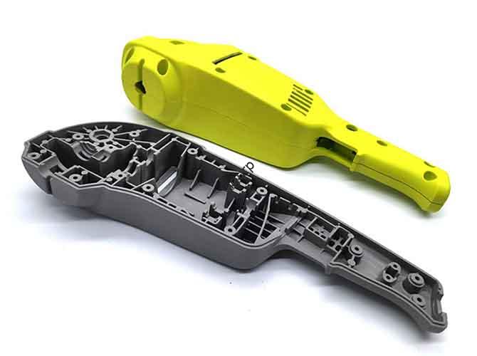
- Konsumgüter: Unternehmen nutzen FDM in großem Umfang, um funktionale Prototypen für ergonomische Tests und Marktfeedback zu erstellen. Dies ermöglicht es ihnen, Designs für Produkte wie Elektrowerkzeuge zu verfeinern, Küchengeräte, und Elektronikgehäuse, bevor Sie sich für teure Spritzgusswerkzeuge entscheiden.
Fallstudie: Eine maßgeschneiderte Drohnenhalterung
Dieses Beispiel veranschaulicht die Leistungsfähigkeit von FDM für die agile Produktentwicklung.
- Die Herausforderung: Ein Ingenieurteam benötigte eine maßgeschneiderte Halterung, um eine neue Sensornutzlast an einer vorhandenen kommerziellen Drohne zu befestigen. Um die Flugzeit zu verlängern, musste die Halterung leicht sein, stark genug, um Vibrationen und harten Landungen standzuhalten, und innerhalb von drei Tagen für einen kritischen Feldtest entworfen und produziert.
- Warum FDM gewählt wurde: Die Wahl war klar. FDM bot eine unübertroffene Geschwindigkeit für die Iteration, Keine Werkzeugkosten, und Zugriff auf eine Reihe von Materialien mit unterschiedlichen Eigenschaften. Für einen einmaligen Prototyp wäre die Bearbeitung des Teils zu langsam und zu teuer gewesen.
- Der Prozess in Aktion:
1. Iteration 1 (PLA): Das ursprüngliche Design wurde in nur zwei Stunden in PLA gedruckt. So schnell, Der kostengünstige Druck wurde lediglich zur Überprüfung der Passung und der Ausrichtung der Montagelöcher verwendet. Der Test ergab ein Problem mit der Freigabe eines der Arme der Drohne.
2. Iteration 2 (PETG): Das CAD-Modell wurde angepasst, um das Spielproblem zu beheben. Das Teil wurde dann in PETG nachgedruckt, ein stärkeres Material, einen Funktionstest durchzuführen. Die Halterung passt perfekt, Ein statischer Belastungstest zeigte jedoch eine potenzielle Schwachstelle in der Nähe einer Schraubennabe.
3. Endgültiges Design (Kohlefaser-Nylon): Das Modell wurde mit einer dickeren Wand und einer Ausrundung an der Schwachstelle verstärkt. Für die endgültige Version, Das Team verwendete ein mit Kohlefasern gefülltes Nylonfilament. Dieses Verbundmaterial sorgte für die hohe Steifigkeit und das geringe Gewicht, die für das flugfertige Teil erforderlich waren.
- Das Ergebnis: Das Team entwickelte sich vom ersten Konzept zum Erfolg, praxiserprobter Funktionsprototyp in unten 48 Std.. Die gesamten Materialkosten lagen unter $20, ein winziger Bruchteil dessen, was eine maschinell bearbeitete Alternative gekostet hätte. FDM ermöglichte einen schnellen, Iterativer Designprozess, der zu einer Optimierung führte, On-Demand-Lösung.
Die Zukunft von FDM
Fused Deposition Modeling ist eine ausgereifte Technologie, aber es ist alles andere als statisch. Kontinuierliche Materialinnovation, Hardware, und Software verschiebt die Grenzen des Möglichen und erweitert ihre Rolle in der Fertigungslandschaft.
Innovationen in Materialien
- Kontinuierliche Faserverstärkung: Es entstehen Systeme, die einen durchgehenden Kohlenstofffaserstrang einbetten, Glasfaser, oder Kevlar in einem Kunststoffteil, während es gedruckt wird, Herstellung von Bauteilen mit einem Festigkeits-Gewichts-Verhältnis, das mit Aluminium vergleichbar ist.
- Fortschrittliche Polymere: Die Entwicklung neuer biokompatibler und bioabsorbierbarer Materialien öffnet Türen für FDM in medizinischen Implantaten und im Tissue Engineering.
Fortschritte in Hardware und Software
- Erhöhte Geschwindigkeit: Neue Bewegungssysteme, High-Flow-Extruder, und ein fortschrittliches Wärmemanagement ermöglichen Druckgeschwindigkeiten, die es sind 5-10 um ein Vielfaches schneller als aktuelle Standards, ohne dass die Qualität darunter leidet.
- KI-gestütztes Schneiden: Zukünftige Slicer-Software wird künstliche Intelligenz nutzen, um die Geometrie eines Modells und die beabsichtigte Anwendung automatisch zu analysieren und Hunderte von Parametern zu optimieren, Schluss mit Rätselraten und ein erfolgreicher Druck beim ersten Versuch.
- Zugänglichkeit erweiterter Funktionen: Funktionen, die einst teuren Industriemaschinen vorbehalten waren, wie zum Beispiel Multimaterialdruck, große Bauvolumina, und beheizte Kammern, werden auf günstigeren Desktop-Systemen zum Standard.
FDM in der Fertigung 4.0
Der bedeutendste Trend ist die Entwicklung von FDM von einem Prototyping-Tool zu einer legitimen Produktionsmethode. Da die Technologie immer schneller wird, zuverlässiger, und in der Lage, stärkere Teile herzustellen, seine Rolle in der digitalen Fabrik wächst. Es ist ein Schlüsselfaktor für die verteilte Fertigung, wo Teile bei Bedarf gedruckt werden können, Nah am Ort des Bedarfs, Revolutionierung der Lieferketten und des Bestandsmanagements.