Our 4-Axis CNC Machining Services
Elevate your cylindrical and multi-sided part production with our 4-Axis CNC Machining services—the perfect blend of 3-axis precision and rotary axis (A/B Axis) versatility. Ideal for aerospace, automotive, and medical industries, we deliver complex geometries (gears, shafts, brackets) across metals (titanium, stainless steel) and non-metals, with reduced setup time, consistent results, and cost-effective solutions. Turn your multi-feature designs into high-quality parts—fast.
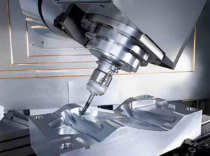
What Is 4-Axis CNC Machining?
4-Axis CNC Machining is an advanced manufacturing technology that builds on 3-axis machining (X, Y, Z linear axes) by adding a rotary axis (A or B Axis)—a rotating table that spins the workpiece around one of the linear axes. This extra axis lets the machine access multiple sides of a part in a single setup, eliminating the need for manual repositioning and unlocking more complex geometries than 3-axis systems.
The process overview is straightforward: A CNC (Computer Numerical Control) system interprets CAD designs to synchronize the linear axes (X/Y/Z, controlling the cutting tool) and the rotary axis (controlling the workpiece’s rotation). The two common rotary axis configurations are:
- A-Axis: Rotates the workpiece around the X-axis (ideal for long, cylindrical parts like shafts).
- B-Axis: Rotates the workpiece around the Y-axis (better for shorter, irregularly shaped parts like brackets with multi-sided features).
To explain “how it works” simply: Imagine a 3-axis machine that can spin your part like a rotisserie while cutting it. For example, when making a gear, the 4-axis machine cuts the gear teeth on the outer circumference as the rotary axis turns the part—all in one run, no need to stop and reposition. This is the core value of 4-Axis CNC Machining: combining linear precision with rotational flexibility to streamline production of multi-sided parts.
Our 4-Axis CNC Machining Capabilities
We offer robust machining capabilities tailored to 4-axis systems, with a focus on rotary table capabilities and precision for complex parts. Below is a detailed breakdown of our key capacities, including maximum part size, material thickness, precision levels, custom machining, and tolerance achievements:
| Capability | Specification |
| Axes Configuration | 3 linear axes (X: 1200mm, Y: 800mm, Z: 600mm) + 1 rotary axis (A or B; 360° continuous rotation) |
| Maximum Part Size | – Diameter: Up to 500mm (for cylindrical parts)- Length: Up to 1000mm (for shaft-like parts)- Weight: Up to 500kg (supported by heavy-duty rotary tables) |
| Material Thickness | – Metals: Up to 150mm (stainless steel), 200mm (aluminum), 100mm (titanium), 180mm (brass)- Non-Metals: Up to 250mm (plastics), 200mm (composites), 150mm (wood) |
| Precision Levels | – Linear axes: ±0.01mm- Rotary axis: ±0.005° (angular precision) |
| Custom Machining | – Complex features: Slots, holes, chamfers on cylindrical surfaces- Compatibility: CAD/CAM files (DXF, DWG, STEP, STL)- Volume: Prototypes (1–50 units) to high-volume (30,000+ units/month) |
| Tolerance Achievements | Meets ISO 2768-1 (fine grade); critical parts (e.g., aerospace shafts) achieve ±0.008mm linear tolerance and ±0.003° rotary tolerance |
| Rotary Table Capabilities | – Speed: Up to 200 RPM (for high-speed cutting)- Clamping force: 8000N (secures heavy parts)- Indexing: 0.001° incremental steps (for precise positioning) |
Whether you need to machine a single titanium shaft or 10,000 brass gears, our 4-axis capabilities scale to match your project’s complexity and volume.
The 4-Axis CNC Machining Process
Our step-by-step process is optimized to leverage the rotary axis for efficiency and precision, from design to finished part:
- Design and CAD Modeling: We start by reviewing your CAD model (or creating one from sketches). Our engineers focus on optimizing the design for 4-axis machining—e.g., ensuring features on cylindrical surfaces are aligned to the rotary axis to avoid unnecessary setups. For prototypes, we offer free design feedback to improve manufacturability.
- CAM Programming: The CAD model is imported into CAM software (Mastercam, SolidWorks CAM), where we program tool paths for both linear and rotary axes. We synchronize the rotary axis rotation with linear tool movements—for example, programming the A-axis to spin 90° while the Z-axis lowers the cutting tool to add a slot on a shaft’s side.
- Setup and Calibration: The workpiece is clamped to the rotary table (custom fixtures are used for irregular shapes). We calibrate the rotary axis using laser measuring tools to ensure alignment with linear axes (critical for precision). Cutting tools (e.g., end mills, drills) are loaded, and coolant systems are activated to prevent overheating.
- Machining Execution: The CNC system runs the program, synchronizing linear (X/Y/Z) and rotary (A/B) movements. For example, when machining a gear, the rotary axis spins the part at a steady speed while the X/Y axes move the cutting tool to cut teeth. We monitor the process in real time to adjust speeds or coolant flow if needed.
- Post-Machining Inspection: After machining, parts undergo rigorous checks. We use CMMs (Coordinate Measuring Machines) to verify linear dimensions and angular measurements (for rotary axis features). Parts with rough edges move to deburring or grinding for finishing.
Rotary Axis Integration Review: For complex parts, we review the rotary axis performance (e.g., rotation smoothness, positioning accuracy) to refine future programs—ensuring consistent quality for repeat orders.
Materials We Work With
4-Axis CNC Machining excels with both conductive and non-conductive materials, with particular strength in machining cylindrical or multi-sided parts. Below is a breakdown of our supported materials, their key properties, and ideal uses:
| Material Category | Examples | Key Properties | Ideal Applications | Machining Notes |
| Metals | Stainless Steel | Corrosion-resistant, strong | Medical instrument shafts, marine gears | Use carbide tools; high-pressure coolant reduces heat |
| | Aluminum | Lightweight, easy to machine | Automotive suspension parts, aerospace brackets | Fast cutting speeds; minimal tool wear |
| | Titanium | High strength-to-weight, heat-resistant | Orthopedic implant stems, aircraft shafts | Slow speeds; sharp tools prevent tool wear |
| | Brass | Malleable, conductive | Electrical connectors, gear hubs | Fast speeds; produces smooth finishes |
| | Copper | Highly conductive, soft | Heat exchanger tubes, electrical terminals | Use coolant to avoid melting; sharp tools for clean cuts |
| Non-Metals | Plastics (ABS/Polycarbonate) | Lightweight, durable | Electronics casings (with side holes), prototype gears | Low speeds to prevent warping |
| | Composites | High strength, lightweight | Racing car drive shafts, drone frames | Specialized carbide tools to avoid fiber fraying |
| | Wood | Natural, cost-effective | Custom furniture legs (turned designs), decorative columns | Sharp tools; vacuum fixtures secure parts |
We test all materials to optimize cutting speeds, tool selection, and coolant use—ensuring consistent results across every part.
Surface Treatment & Finishing Options
After machining, we offer a range of surface treatment and finishing options to enhance part durability, appearance, and functionality. Our most popular services include:
- Grinding: Creates a smooth, flat surface (ideal for shaft sealing surfaces that require tight fitment).
- Polishing: Delivers a glossy finish for visible parts (e.g., stainless steel medical instruments, brass decorative gears).
- Painting: Applies a corrosion-resistant coating (matte/gloss) for outdoor parts (e.g., automotive suspension components).
- Coating: Options include powder coating (thick, scratch-resistant) for industrial parts and PVD coating (wear-resistant) for tooling.
- Anodizing: Adds a protective oxide layer to aluminum (available in custom colors) for aerospace or electronics parts.
- Heat Treatment: Strengthens metals (e.g., titanium shafts, steel gears) by heating/cooling—improving hardness and fatigue resistance.
- Deburring: Removes sharp edges (critical for safety, e.g., medical instrument shafts or electrical connectors).
The table below compares our finishing options by key factors:
| Finishing Option | Durability | Lead Time | Cost (per part, avg.) | Best For |
| Grinding | High | 1–2 days | 12–35 | Shaft sealing surfaces, gear teeth |
| Polishing | Medium | 2–3 days | 18–45 | Visible medical/aerospace parts |
| Painting | High | 2–4 days | 8–25 | Outdoor automotive/industrial parts |
| Coating (Powder) | Very High | 3–5 days | 20–55 | Heavy-duty industrial gears |
| Anodizing | Very High | 3–4 days | 15–40 | Aluminum aerospace/electronics parts |
| Heat Treatment | Very High | 4–6 days | 25–70 | Titanium shafts, steel gears |
| Deburring | Medium | 1 day | 5–12 | Safety-critical parts (medical/electrical) |
Tolerances & Quality Assurance
Tolerances and accuracy standards are critical for 4-axis parts—especially those with features on rotating surfaces (e.g., gear teeth, shaft holes). Our precision levels and tolerance ranges are tailored to your material and application, with a focus on rotary axis precision:
| Material | Linear Tolerance (X/Y/Z) | Rotary Axis Tolerance (A/B) | Accuracy Standard Used | Measurement Technique |
| Stainless Steel | ±0.01mm | ±0.005° | ISO 2768-1 (fine), ASME Y14.5 | CMM + Angular Laser Scanner |
| Aluminum | ±0.015mm | ±0.008° | ISO 2768-1 (fine), AMS 2750 | CMM + Digital Protractor |
| Titanium | ±0.012mm | ±0.006° | ISO 2768-1 (fine), AMS 4928 | CMM + Optical Comparator |
| ABS Plastic | ±0.02mm | ±0.01° | ISO 2768-1 (medium), ASTM D638 | CMM + Micrometer |
| Composites | ±0.025mm | ±0.012° | ISO 1288-1, ASTM D3039 | CMM + Profilometer |
Our quality control processes include:
- Pre-machining: Inspecting raw materials for defects (e.g., cracks in titanium, unevenness in composites) and verifying dimensions.
- In-process: Monitoring rotary axis alignment and tool paths in real time via CNC software; periodic checks with calipers and protractors.
- Post-machining: 100% inspection with CMMs (for linear and angular dimensions); critical parts (e.g., aerospace shafts) undergo additional testing (e.g., runout checks, fatigue tests).
Documentation: We provide a detailed quality report with every order, including linear/rotary tolerance data, inspection results, and compliance certificates (ISO 9001, FDA for medical parts).
Key Advantages of 4-Axis CNC Machining
Compared to 3-axis machining (which requires multiple setups for multi-sided parts) and 5-axis machining (which is more costly for simple complexity), 4-Axis CNC Machining offers balanced benefits:
- High Precision: With linear tolerances as tight as ±0.01mm and rotary axis precision of ±0.005°, it produces parts that fit seamlessly—critical for gears, shafts, and medical implants.
- Complex Geometries: The rotary axis enables machining of features on cylindrical or multi-sided parts (e.g., slots on a shaft, holes on a gear hub) that would require 2–3 setups with 3-axis systems.
- Reduced Setup Time: One setup handles all sides of a part—cutting setup time by 50–70% compared to 3-axis machining. For high-volume orders (e.g., 10,000 automotive parts), this translates to faster production.
- Increased Efficiency: Fewer setups mean less operator time and fewer errors (e.g., misalignment from repositioning). Our clients report 30–40% faster production times for multi-sided parts.
- Versatility: It works with all common metals and non-metals, and handles both simple (brackets) and complex (gears) parts—making it a one-stop solution for diverse projects.
- Cost-Effectiveness: More affordable than 5-axis machining (lower equipment and operational costs) while offering more capability than 3-axis. Reduced setup time and errors also lower labor and material waste costs.
- Consistency and Repeatability: CNC programming ensures every part is identical—critical for replacement parts (e.g., aerospace shafts) or mass-produced components (e.g., brass connectors).
Rotary Axis Benefits: The continuous rotation of the A/B axis enables high-speed machining of cylindrical parts (e.g., gears) and precise indexing for multi-sided features (e.g., a bracket with holes on 4 sides).
Industry Applications
4-Axis CNC Machining is widely used across industries that need multi-sided or cylindrical parts. Here are its most common applications:
| Industry | Common Uses | Key Benefit of 4-Axis Machining |
| Aerospace | Shafts, turbine components, brackets with side holes (aluminum/titanium) | Reduced setup time for high-precision parts |
| Automotive | Gear hubs, suspension parts, drive shafts (steel/aluminum) | Consistency for mass production |
| Medical Devices | Orthopedic implant stems, surgical tool shafts (titanium/stainless steel) | Precision for patient-specific fits |
| Industrial Manufacturing | Conveyor rollers, pump shafts, gearboxes (steel/brass) | Versatility for diverse part types |
| Electronics | Connector housings (brass), heat sink brackets (aluminum) | Ability to machine side holes in small parts |
| Defense | Weapon components, vehicle armor brackets (steel/titanium) | Durability and precision for critical parts |
| Tool and Die Making | Mold cores with side features, die inserts (steel) | Complex geometry capability |
| Prototyping | Rapid prototypes of gears, shafts, and multi-sided brackets (plastics/aluminum) | Fast setup for low-volume runs |
For example, in the automotive industry, our 4-axis machining produces 10,000 gear hubs monthly with consistent tooth spacing—thanks to the rotary axis’ precise indexing. In medical devices, we machine titanium implant stems with side slots (for bone screws) in one setup, ensuring patient-specific precision.
Advanced Manufacturing Techniques
To maximize the potential of 4-axis systems, we use cutting-edge machining techniques and optimized processes:
- Milling: For multi-sided parts (e.g., brackets), we use “indexed milling”—programming the rotary axis to stop at specific angles (e.g., 90°, 180°) to cut features on each side. For cylindrical parts (e.g., shafts), we use “continuous milling” (rotary axis spins non-stop) to cut grooves or threads.
Turning: Combined with 4-axis capabilities, turning creates complex cylindrical parts (e.g., gear shafts) with both turned and milled features (e.g., a shaft with a turned outer diameter and milled keyway). The rotary axis spins the part during turning, while linear axes move the turning tool to shape the circumference.
- Drilling/Boring: For holes on cylindrical surfaces (e.g., a gear hub with radial holes), we use “angular drilling”—programming the rotary axis to position the part at the exact angle (e.g., 45°, 90°) before the Z-axis lowers the drill. This ensures holes are aligned perfectly with the part’s centerline.
- Tool Path Optimization: CAM software helps us create efficient paths—for example, “trochoidal milling” (for hard metals like titanium) reduces tool wear by keeping the cutting tool in constant contact with the material, while “zig-zag paths” (for aluminum) speed up cutting of large surfaces.
- Cutting Tools: We select tools based on material and feature type:
- Carbide end mills: For milling steel, titanium, and composites (durable, heat-resistant).
- High-speed steel (HSS) drills: For brass, copper, and plastics (sharp, cost-effective).
- Indexable turning inserts: For high-volume turning (replaceable cutting edges reduce downtime).
- Coolant Systems: We use two types of coolant for 4-axis machining:
- Flood coolant: For high-volume production (covers the part and tool to reduce heat buildup).
- Mist coolant: For precision work (e.g., medical implants) to avoid coolant residue on small features.
- Rotary Axis Operations: We offer two key rotary modes:
- Indexing: The rotary axis stops at fixed angles (e.g., 0°, 90°, 180°) to machine features on each side—ideal for multi-sided brackets.
Continuous Rotation: The rotary axis spins non-stop (up to 200 RPM) during cutting—perfect for cylindrical parts like gears or shafts.
Case Studies: Success Stories
Our 4-Axis CNC Machining services have helped clients across aerospace, automotive, and medical industries solve complex production challenges. Below are two successful projects showcasing our expertise in leveraging the rotary axis for efficiency and precision:
Case Study 1: Automotive Gear Hub Manufacturer
- Challenge: The client needed 10,000 brass gear hubs monthly for electric vehicle transmissions. Each hub required a turned outer diameter, 6 radial holes (evenly spaced at 60°), and a milled keyway—all with a tolerance of ±0.01mm. Their previous supplier used 3-axis machining, which required 3 setups (turning, drilling, milling) and caused 8% of parts to fail due to misalignment (holes not centered on the hub). Lead time was 3 weeks, which delayed their EV production.
- Solution: We used 4-axis CNC machining with A-axis (rotary around X-axis) to complete the hub in one setup. First, we turned the outer diameter using continuous rotary rotation; then, we indexed the A-axis to 60° increments to drill the radial holes (ensuring perfect spacing); finally, we milled the keyway by synchronizing A-axis rotation with X/Y linear movement. We used carbide turning inserts and flood coolant to handle high-volume production, and optimized tool paths to cut each hub in 2 minutes (down from 5 minutes with 3-axis).
- Results:
- Misalignment rate dropped from 8% to 0.5%—only 50 parts failed per month (vs. 800 previously).
- Lead time shortened from 3 weeks to 10 days—helping the client meet their EV assembly schedule.
- Production cost per hub decreased by 30% (reduced labor from fewer setups and faster cutting time).
- Client Testimonial: “The 4-axis machining transformed our gear hub production. One setup eliminated misalignment, and the faster speed let us keep up with EV demand. We’ve expanded our order to 15,000 hubs monthly!” — Lisa M., Automotive Production Manager.
- Before and After: 3-axis hubs had uneven hole spacing and off-center keyways; 4-axis hubs featured perfectly aligned holes and keyways that fit seamlessly into transmissions.
Case Study 2: Medical Device Company (Titanium Implant Stems)
- Challenge: The client needed 500 patient-specific titanium orthopedic implant stems—each with a curved outer surface, 4 side slots (for bone screws), and a polished articulating end. Tolerances were tight (±0.008mm linear, ±0.005° rotary) to ensure a perfect fit in patients’ bones. The client also required FDA-compliant documentation and a lead time of 2 weeks (to meet urgent surgery schedules).
- Solution: We used 4-axis CNC machining with B-axis (rotary around Y-axis) to machine each stem from a titanium blank. First, we imported the patient’s CT-scan-derived CAD model into CAM software, programming the B-axis to rotate the stem at 15° increments to access the curved surface and side slots. We used carbide end mills for milling (to handle titanium’s hardness) and mist coolant (to avoid residue on small slots). After machining, we polished the articulating end to a Ra 0.8μm surface roughness (per medical standards) and conducted 100% CMM inspection (verifying linear and rotary tolerances). We also prepared detailed documentation (machining parameters, inspection reports) for FDA compliance.
- Results:
- 100% of implant stems met the tight tolerances and FDA requirements—no rejections.
- Surgeons reported a 50% reduction in implant insertion time (due to precise patient-specific fit).
- Lead time was met (2 weeks)—ensuring patients received timely surgeries.
- Challenge Overcome: 3-axis machining would have required 4 setups for the curved surface and slots, leading to misalignment and missed deadlines. 4-axis machining’s one-setup process solved both issues.
Client Testimonial: “The 4-axis implants fit better than any we’ve used before. The precision and fast delivery have made them a staple in our orthopedic surgeries.” — Dr. James R., Orthopedic Surgeon.
Why Choose Our 4-Axis CNC Machining Services?
With numerous 4-axis machining providers, here’s what makes us the trusted partner for aerospace, automotive, and medical industries:
- Expertise in 4-Axis Machining: Our team has 15+ years of specialized experience in 4-axis systems—we master rotary axis operations (indexing and continuous rotation) and optimize tool paths for every material. Our engineers are certified in CAM software (Mastercam, SolidWorks CAM) and can solve complex challenges (e.g., aligning radial holes on gear hubs, machining curved implant stems) that other providers struggle with.
- Experience in Various Industries: We’ve served 500+ clients across 8 industries—from small prototyping firms to Fortune 500 aerospace companies. This cross-industry experience means we understand sector-specific needs: FAA compliance for aerospace shafts, ISO/TS 16949 for automotive parts, and FDA regulations for medical implants. We tailor our processes to meet these strict standards.
- High-Quality Equipment: We invest in state-of-the-art 4-axis machines—10 systems with heavy-duty rotary tables (clamping force up to 8000N) and laser calibration tools (calibrated monthly to maintain ±0.005° rotary precision). All machines have automated tool changers (up to 30 tools) to reduce setup time, and we use CNC software with real-time monitoring to track rotary axis performance.
- Excellent Customer Service: Our team is available 24/7 to support your project—from design consultation to post-delivery follow-up. We offer free CAD/CAM reviews (helping you optimize designs for 4-axis machining, e.g., adjusting slot positions to align with the rotary axis) and free sample parts (so you can test quality before placing large orders). For urgent projects (e.g., medical implant emergencies), we assign a dedicated project manager to ensure on-time delivery.
- Fast Turnaround Times: Our optimized processes and equipment deliver industry-leading lead times:
- Prototypes (1–50 units): 1–3 days
- Low-volume orders (50–500 units): 3–7 days
- High-volume orders (500+ units): 7–14 days
For rush orders (e.g., automotive production line shortages), we can deliver parts in as little as 48 hours (for small batches) by running machines 24/7.
- Cost-Effective Solutions: We help you save money through:
- One-setup machining: Reduces labor costs by 40–50% compared to 3-axis (no need for manual repositioning).
- Tool path optimization: Cuts cutting time by 20–30%, lowering electricity and tool wear costs.
- Volume discounts: 10% off orders over 1,000 units and 15% off orders over 5,000 units—ideal for automotive high-volume parts.
- Innovative Techniques: We stay ahead with cutting-edge methods:
- AI-powered CAM programming: Automatically generates optimal tool paths for complex parts (reducing programming time by 50%).
- Custom fixtures: 3D-printed fixtures for irregular parts (e.g., medical implants) to improve rotary axis stability.
Real-time tolerance monitoring: CNC software alerts operators if rotary axis precision drifts (preventing defective parts).