In der schnelllebigen Luft- und Raumfahrtindustrie, 3D Printed Aerospace Prototype Modelle sind ein Game-Changer geworden. Sie ermöglichen Ingenieuren, neue Designs zu testen, Leistung validieren, und Reduzierung von Entwicklungszyklen - kritisch, um in einer Branche in einer Branche zu bleiben, in der jeden Tag und jeder Dollar zählt. Jedoch, effektiv schaffen 3D gedruckte Luft- und Raumfahrtprototypen ist nicht einfach. Herausforderungen wie die Auswahl des Rechts Additive Fertigung Technologie, Auswahl von Materialien für Luft- und Raumfahrt, und sicherstellen, dass Prototypen strenge Leistungsstandards erfüllen. Dieser Artikel bricht den gesamten Prozess um vier Kernthemen ab, Bieten Sie umsetzbare Lösungen für gemeinsame Probleme und helfen Ihnen dabei, qualitativ hochwertige Luft- und Raumfahrtprototypen effizient aufzubauen.
1. 3D Drucktechnologie: Wählen Sie das richtige Werkzeug für Luft- und Raumfahrtanforderungen
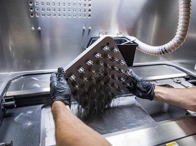
3D Drucktechnologie ist die Grundlage für die Entwicklung des Luft- und Raumfahrtprototyps. Unlike consumer-grade 3D printing, aerospace prototypes demand precision, Haltbarkeit, and compatibility with specialized materials. Selecting the right technology—from FDM Zu Sls—depends on the prototype’s purpose (Z.B., bilden, fit, or function testing) und Leistungsanforderungen.
1.1 Comparison of 3D Printing Technologies for Aerospace Prototypes
| Technologie | Arbeitsprinzip | Key Advantages for Aerospace | Limitations for Aerospace | Ideal Prototype Types |
| Modellierung der Ablagerung (FDM) | Melts thermoplastic filaments (Z.B., ABS, Schmalz) and extrudes them layer-by-layer | Niedrige Kosten; compatible with aerospace-grade polymers (Z.B., SPÄHEN); easy to scale for large parts | Geringe Präzision (layer height ≥0.1mm); weak layer adhesion (risk of delamination under stress) | Large-scale Maßstabsmodelle (Z.B., aircraft fuselage sections); non-load-bearing components (Z.B., avionics housings for fit testing) |
| Stereolithikromographie (SLA) | Uses UV light to cure liquid photopolymers into solid layers | Hohe Präzision (layer height ≥0.025mm); glatte Oberfläche (Ra ≤0,8μm); ideal for detailed parts | Brittle parts (Schlechte Aufprallfestigkeit); limited material options (mostly photopolymers, kein Metall) | Klein, detaillierte Prototypen (Z.B., satellite antenna components); conceptual design models for aerodynamic testing |
| Selektives Lasersintern (Sls) | Uses a laser to sinter powdered materials (Z.B., Nylon, Metalllegierungen) into layers | Keine Unterstützungsstrukturen erforderlich; hohe Teildichte (>95%); compatible with metal (Z.B., Titan) | Hohe Kosten; slow build speed (20-50 mm/h); requires post-sintering (Z.B., HIPing for metals) | Funktionelle Prototypen (Z.B., aircraft bracket prototypes for load testing); Komplexe Geometrien (Z.B., lattice structures for lightweighting) |
Eine gemeinsame Frage hier ist: When should I use SLS over FDM for aerospace prototypes? If your prototype needs to withstand mechanical stress (Z.B., a wing rib prototype for load testing) or has complex internal geometries (Z.B., a fuel injector model), SLS is better—it produces stronger, langlebigere Teile. For low-cost, large-scale fit-testing models (Z.B., checking if a new avionics unit fits in the cockpit), FDM is the more practical choice.
2. Aerospace Industry Requirements: Align Prototypes with Strict Standards
Der Luft- und Raumfahrtindustrie has some of the most rigorous standards in manufacturing—prototypes are no exception. From material compatibility to performance under extreme conditions, every aspect of a 3D printed aerospace prototype must align with industry norms (Z.B., ASTM F3300 for 3D printed aerospace parts).
2.1 Key Aerospace Requirements for 3D Printed Prototypes
| Requirement Category | Specific Standards | Impact on Prototype Development |
| Aerospace Materials | Polymere: SPÄHEN (melting point 343℃), Schmalz (chemischer Widerstand); Metalle: Ti-6al-4V (hohe Kraft-Gewicht), Inconel 718 (Wärmewiderstand) | Avoid low-grade materials (Z.B., standard ABS)—they fail under extreme temperatures/pressures. Zum Beispiel, a prototype for engine components must use Inconel 718 (withstands 650℃+), not nylon. |
| Performance Under Extremes | Temperaturbereich (-60℃ to 200℃ for most components); Druck (bis zu 10 bar for hydraulic parts); Vibration (20-2000 Hz for aircraft engines) | Prototypes must undergo environmental testing. For a satellite prototype, test it at -60℃ (space-like conditions) to ensure it doesn’t crack; for an aircraft engine part, test vibration resistance to avoid fatigue failure. |
| Avionics Compatibility | Elektrische Isolierung (for parts near wiring); electromagnetic interference (EMI) shielding (for communication components) | For a prototype avionics housing, use FDM with carbon-fiber-reinforced PEEK (provides EMI shielding); avoid SLA photopolymers (poor electrical insulation). |
| Lightweighting | Target weight reduction (10-30% vs. Traditionelle Teile); Hochfestes Verhältnis (≥200 MPa/(g/cm³)) | Use SLS to print lattice structures—they reduce weight by 25% während der Stärke aufrechterhalten. Zum Beispiel, an aircraft bracket prototype with a lattice core weighs 30% less than a solid one but can still support 500 N of load. |
3. Prototypentwicklung: From Concept to Functional Test
Prototypentwicklung for aerospace is an iterative process—from early conceptual design to final Funktionelle Prototypen. Rushing this process often leads to costly rework; following a structured approach ensures prototypes meet goals without delays.
3.1 Step-by-Step Aerospace Prototype Development Process
- Conceptual Design: Define the prototype’s purpose (Z.B., aerodynamic testing, fit validation) and key requirements (Z.B., Gewicht, Temperaturwiderstand). Use sketching or simple 3D models to explore 2-3 design variants. Zum Beispiel, when designing a new aircraft winglet prototype, sketch variants with different angles (15°, 20°, 25°) to test aerodynamic efficiency.
- Schnelles Prototyping: Use low-cost 3D printing (Z.B., FDM for large parts, SLA for small details) to create early-stage prototypes. Focus on form and fit, not function. This step helps identify design flaws early—for instance, a FDM-printed cockpit panel prototype might reveal that a new switch is too close to a display, making it hard to reach.
- Iterative Design: Test the rapid prototype, gather feedback, and refine the design. Repeat this 2-3 times to fix issues like poor ergonomics or incompatible dimensions. Zum Beispiel, if a SLA-printed satellite antenna prototype has weak signal reception, adjust the antenna’s curvature and reprint a new version.
- Funktionales Prototyping: Use high-performance 3D printing (Z.B., SLS for metal parts, FDM with PEEK) to create prototypes that mimic the final part’s function. Nachbearbeitung hinzufügen (Z.B., Schleifen, Malerei, oder Wärmebehandlung) Leistung zu verbessern. A functional wing rib prototype, Zum Beispiel, might be SLS-printed with Ti-6Al-4V and heat-treated to increase tensile strength to 900 MPA.
- Testen und Validierung: Subject the functional prototype to aerospace-specific tests:
- Aerodynamic testing (wind tunnel tests to measure drag/lift).
- Load testing (anwenden 120% of the expected load to ensure durability).
- Umwelttests (expose to extreme temperatures, Luftfeuchtigkeit, oder Vibration).
4. Modellierung und Simulation: Predict Performance Before Printing
Modellierung und Simulation are critical for aerospace prototypes—they let you test performance virtually, reducing the need for physical prototypes and cutting costs. Werkzeuge wie CAD software and Fea help optimize designs and catch issues before 3D printing.
4.1 Key Simulation Tools and Their Uses
| Werkzeug/Methode | Zweck | Practical Application Example |
| Computergestütztes Design (CAD) | Create detailed 3D models with precise dimensions (tolerance ±0.01mm) | Use SolidWorks to design a aircraft landing gear prototype—add features like holes for bolts and fillets to reduce stress concentration. |
| Finite -Elemente -Analyse (Fea) | Simulate mechanical stress, strain, and fatigue to predict failure | Run FEA on a SLS-printed engine bracket prototype—apply 500 N of load to see if the bracket bends (max allowable deflection: 0.5mm). If it bends 0.8mm, thicken the bracket’s walls. |
| Computational Fluid Dynamics (CFD) | Simulate fluid flow (Luft, fuel) to optimize aerodynamics or fuel efficiency | Use CFD to test a FDM-printed aircraft wing prototype—adjust the wing’s angle of attack to reduce drag by 15%. |
| Virtual Prototyping | Combine CAD, Fea, and CFD to create a digital twin of the prototype | Build a virtual twin of a satellite prototype—simulate its orbit, Temperaturänderungen, and signal reception to ensure it works in space before printing. |
A common challenge here is: How do I ensure simulation results match real-world performance? Calibrate your simulation software with material data from the 3D printer manufacturer. Zum Beispiel, if you’re simulating a PEEK prototype, use the actual tensile strength (90 MPA) and modulus (3.6 GPA) of the PEEK filament you’re using—don’t rely on generic material data, which can be inaccurate by 10-15%.
5. Yigu Technology’s Perspective on 3D Printed Aerospace Prototypes
Bei Yigu Technology, Wir konzentrieren uns auf “simulation-driven, performance-first” for 3D printed aerospace prototypes. We use SLS for metal functional parts (Ti-6al-4V, Inconel 718) and FDM with PEEK for polymers, ensuring material compliance with ASTM F3300. Our workflow integrates CAD (Solidworks) + Fea (Ansys) + CFD (Fluent) to predict performance—cutting physical prototype needs by 40%. For testing, we conduct wind tunnel and -60℃ to 200℃ environmental tests. The core is balancing speed (rapid prototyping in 3-5 Tage) and aerospace rigor—delivering prototypes that bridge design and flight-ready parts.
FAQ
1. What 3D printing technology is best for aerospace prototypes that need to withstand high temperatures?
For high-temperature aerospace prototypes (Z.B., Motorkomponenten, satellite parts exposed to solar radiation), SLS is ideal—especially when using heat-resistant materials like Inconel 718 (withstands up to 650℃) oder schauen (melting point 343℃). SLA is not recommended (photopolymers degrade above 80℃), and FDM works only if using high-performance filaments (Z.B., Schmalz) instead of standard plastics.
2. How can I reduce the cost of 3D printed aerospace prototypes without sacrificing quality?
Focus on iterative design with low-cost rapid prototyping first: Use FDM (für große Teile) oder SLA (for small details) to test form/fit in early stages—these technologies cost 50-70% less than SLS. Only use high-cost technologies (Z.B., SLS for metal) Für funktionelle Prototypen. Auch, optimize the design for 3D printing (Z.B., reduce support structures, use lattice cores) to cut material waste by 20-30%.
3. Do 3D printed aerospace prototypes need post-processing?
Yes—post-processing is critical for meeting aerospace standards. For FDM prototypes: Sand layers to improve surface finish (Ra from 3.2μm to 1.6μm) and heat-treat (Z.B., anneal PEEK at 200℃) to strengthen layer adhesion. For SLS metal prototypes: Use hot isostatic pressing (HÜFTE) to eliminate pores (Erhöht die Dichte auf > 99%) und kritische Oberflächen von CNC -Maschinen (um ± 0,01 mm Toleranz zu erreichen). Für SLA -Prototypen: Unter UV -Licht heilen für 2-4 Stunden zur Reduzierung der Sprödigkeit.